While teaching myself Microsoft DirectX, I fell into an issue that is best described as "invisible geometry". This is the unfortunate situation when lines aren't appearing when and where you expect them to. You've told DirectX to draw something, but you don't see it. The difficulties with getting this simple "two-faced triangle" to draw seemed to represent the difficulties with working with DirectX in general.
Here was the picture I was trying to draw:
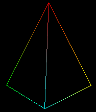
Each vertex, aka "point", in this "fan" of triangles is labeled. Here's the picture in the X-Y coordinate system.
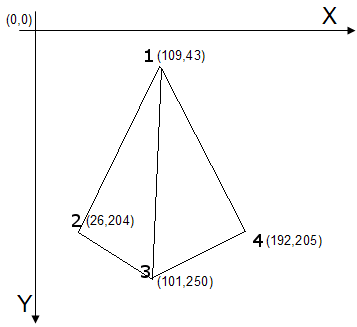
Point 1 is in the X-Y location of (109, 43), Point 2 is (26, 204), Point 3 is (101, 250), and Point 4 is (192, 205). (To keep things simple, all points share the same 'z'.) In the program, the points are defined like this:
{ 109.0f, 43.0f, 0.5f, 1.0f, 0xffff0000, }, // 1: x, y, z, rhw, color // red
{ 26.0f, 204.0f, 0.5f, 1.0f, 0xff00ff00, }, // 2: green
{ 101.0f, 250.0f, 0.5f, 1.0f, 0xff00ffff, }, // 3: blue
{ 192.0f, 205.0f, 0.5f, 1.0f, 0xffffff00, }, // 4: yellow
};
Asking DirectX's DrawPrimitive() to render a "triangle fan" from these points should produce the picture above (a triangle fan shares the first vertex). However, the program produced an empty window. My "geometry" was invisible.
Casting about the Internet found the helpful "Solving Invisible Geometry" web page. The author, Keith Ditchburn, offers plenty of suggestions for what to check when lines are "invisible", including checking the error messages inside of Visual Studio, checking return codes from the DirectX calls, and making sure the model is not out of the view. But the most compelling hint on his page is the one about "Correct Winding."
Keith writes: "You must define your triangles by specifying vertex in clockwise order. This is essential because internally Direct3D knows that if the winding is counter clockwise the triangle must be facing away from the camera and so does not need rendering. ... Remember to define the clockwise order in terms of looking at the face head on. If baffled create an object out of paper and label it, then rotate it to see the correct vertex order."
Order was important! Hacking away, as a test, I changed the order of my vertices to:
{ 109.0f, 43.0f, 0.5f, 1.0f, 0xffff0000, }, // 1: x, y, z, rhw, color // red
{ 192.0f, 205.0f, 0.5f, 1.0f, 0xffffff00, }, // 4: yellow
{ 26.0f, 204.0f, 0.5f, 1.0f, 0xff00ff00, }, // 2: green
{ 101.0f, 250.0f, 0.5f, 1.0f, 0xff00ffff, }, // 3: blue
};
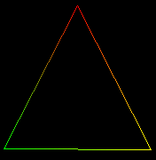
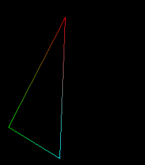
In the change above, I moved my last vertex to the second position. This change produced a visible triangle!
But where was my "second triangle"? I reread Keith's advice some more. "You must define your triangles by specifying vertex in clockwise order. This is essential because internally Direct3D knows that if the winding is counter clockwise the triangle must be facing away from the camera ..."
What was this 'winding' business? 'Winding' didn't make sense until after reading an excerpt from "Drawing in Space". The 'order' of the vertices implies a direction! With my vertices at 1-4-2-3, my 'winding' was 'clockwise' for the 1-4-2 triangle:
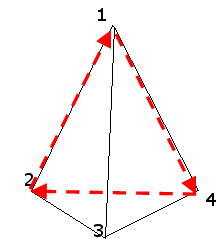
In the above diagram, starting with Point 1, then to Point 4, then Point 2, then back to Point 1, the "direction" of the arrows is "clockwise." But for the second triangle, the triangle defined by 1-2-3, my winding was 'counter clockwise':
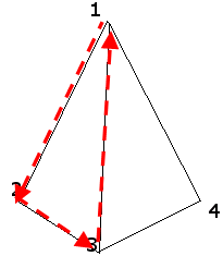
In the diagram above, starting with Point 1, then to Point 2, then to Point 3, then back to Point 1, the direction of the arrows is "counter clockwise."
Was there a way to test this understanding? Yes. Before you call DrawPrimitive(), set the CULLMODE to clockwise.
Culling, or removing, is what DirectX does when it removes vertices that are following a counter clockwise winding. By reversing the 'cull mode', all the triangles that follow a clockwise winding would be removed. And sure enough, with the vertices ordered as 1-4-2-3, setting the cull mode to 'clockwise' caused the 1-2-3 triangle to appear, but NOT the 1-4-2 triangle.
To see both my triangles with the 1-4-2-3 ordering, I could set the 'cull mode' to 'none'.
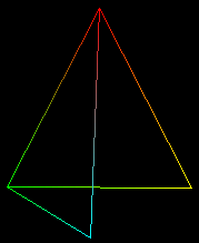
In the picture above, you can see that the 1-2-3 triangle is 'behind' the front facing triangle.
Finally, to draw the original set of triangles, I needed to reorder my vertices so that the second triangle was winding 'clockwise':
{ 109.0f, 43.0f, 0.5f, 1.0f, 0xffff0000, }, // 1: x, y, z, rhw, color // red
{ 192.0f, 205.0f, 0.5f, 1.0f, 0xffffff00, }, // 4: yellow
{ 101.0f, 250.0f, 0.5f, 1.0f, 0xff00ffff, }, // 3: blue
{ 26.0f, 204.0f, 0.5f, 1.0f, 0xff00ff00, }, // 2: green
};
This ordering produces two triangles, with the vertices for both triangles winding clockwise. This enables both triangles to be visible with the default 'cull mode'.
For those of you noodling with or learning DirectX, keep the cull mode in mind whenever you're not seeing what you expect. The 'winding' of your points may not be obvious, but changing the cull mode will let you spot winding issues easily.
View and copy the source code to this example: trianglefan.cpp.